Limiting equilibrium methods
Limiting equilibrium methods are commonly used to assess the required penetration of embedded retaining walls, associated shear forces and bending moments in their cross-sections, and the forces in any props or anchors used to support them. Limiting equilibrium methods assume that the full strength of the ground is mobilized uniformly around the wall, so that the wall is at the point of collapse (or 'limiting equilibrium').
Cantilever walls and walls propped near their top are statically determinate structures that can be analysed using limiting equilibrium methods, as described in Sections 12.4.1 and 12.4.2 below. Multi-propped walls are statically indeterminate structures that can only be analysed using limiting equilibrium methods by introducing significant simplifications to make the structure statically determinate.
12.4.1 Fixed-earth conditions
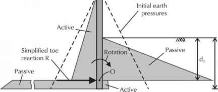
The stability of an embedded cantilever wall can be verified by assuming 'fixed-earth' conditions, as illustrated in Figure 12.4. The wall, which is assumed to rotate about the fixed point 'O', relies on the support of the ground to maintain horizontal and moment equilibrium.
Figure 12.4. Assumed earth pressures acting on an embedded cantilever retaining wall at limiting equilibrium (fixed earth conditions)
Above the point of fixity, ground on the retained (left-hand) side of the wall goes into an active state and that on the restraining (right-hand) side into a passive state. The earth pressures bearing on the wall decrease from their initial, at-rest (K,) values to active (Ka) values on the left and increase towards fully passive (Kp) on the right.

Figure 12.4. Assumed earth pressures acting on an embedded cantilever retaining wall at limiting equilibrium (fixed earth conditions)
Below the point of fixity, ground on the retained side goes into a passive state and that on the restraining side into an active state. The earth pressures below O therefore increase towards fully passive values on the left and decrease to active values on the right.
The situation shown in Figure 12.4 is often simplified by replacing the earth pressures below O with an equivalent reaction R. The depth of embedment (dO) required to ensure moment equilibrium about the point of fixity is then increased by 20% to compensate for this assumption,19 i.e. d = 1.2 dO.
12.4.2 Free-earth conditions
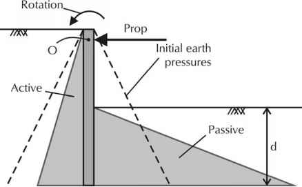
The stability of an embedded wall propped near its top can be verified by assuming 'free-earth' conditions, illustrated in Figure 12.5. The wall, which is assumed to rotate about the fixed point 'O', relies on the support of the ground and prop to maintain moment and horizontal equilibrium.

Figure 12.5. Assumed earth pressures acting on a singly-propped embedded retaining wall at limiting equilibrium conditions (free earth conditions)
Below the point of fixity, ground on the retained (left-hand) side of the wall goes into an active state and that on the restraining (right-hand) side into a passive state. The earth pressures bearing on the wall decrease from their initial, at-rest (K0) values to active (Ka) values on the left and increase towards fully passive (Kp) on the right.
Above the point of fixity, the retained ground goes into a passive state and the restraining ground into an active state. However, to avoid overcomplicating the calculations, earth pressures are treated in the same way above the point of fixity as they are below. This simplification is less easily justified when the prop is located in the lower half of the retained height.
Propped embedded walls may also be verified assuming fixed-earth conditions, but the calculations are more complicated. Fixed-earth conditions suggest a longer pile is needed than free-earth conditions, but the assumed fixity reduces the theoretical bending moment in the pile. Hence if driving is difficult and the full design penetration is not achieved, the stability requirements for free-earth conditions may be satisfied but the moment capacity of the pile may be compromised.

